| |
|
|
| |
|
|
Dynamic Braking Resistors Work
|
|
| |
| Dynamic Braking is a form of electrical braking of electrical motors. Dynamic Braking Resistors (DBRs) are used to absorb the energy generated when stopping electrical motors. They are designed to absorb this energy and to cool down quickly between stops. |
| |
How Dynamic Braking Resistors Work |
State of the art AC Variable Frequency Drives (VFD) are commonplace today, creating the need for reliable, proven Dynamic Braking Resistors, that can be delivered quickly, completely assembled, and ready for convenient installation at the job-site. Dynamic Braking Resistors are used with AC VFD's to produce a braking torque in the motor during overhauling conditions. The Dynamic Braking Resistor is connected across the DC bus and will see voltages as high as 800 Volts.
The drive manufacturer normally determines the power rating (Watts) needed to prevent overheating during braking duty. The peak braking current is determined by the specified resistance value. Each drive manufacturer specifies a resistance range with a minimum to prevent overcurrent and damage to the drive and a maximum value to give adequate lower dissipation capability.
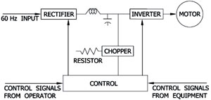
A three-phase variable frequency drive (VFD) consists of three basic components - Rectifier, DC line, and Inverter - and a Control System to manage these three components as illustrated in Figure I. The rectifier converts the three-phase 60 Hz AC input to a DC
signal.
|
 Figure 1
 |
Depending on the system, an inductor, a capacitor, or combination of these components smoothes the DC signal (reduces voltage ripple) in the DC link part of the VFD. The inverter circuit converts the DC signal into a variable frequency AC voltage to control the speed of the induction motor.
During braking, the VFD ramps the frequency to zero. The rotational energy of the motor and load are driven back through the inverter to the DC bus and the rotational energy is dissipated through the resistor.
|
|
We offer DBRs in a wide range of Ohmic value and Current ratings, in compact and economical designs.
For medium and high current ratings, we offer DBRs with Punched Stainless Steel Grids, housed in a well ventilated MS enclosure with IP 21 protection.
For low current ratings, we offer DBRs with a combination of a number of Wire Wound Resistors connected together in series. These Wire Wound Resistors can be offered in open execution (IP 00) or in an MS enclosure with IP 21 protection.
|
|
Details required to design a Dynamic Braking Resistors Work : |
| 1. Ohmic Value |
| 2. Wattage |
| 3. Duty Cycle (Time ON / Time OFF) |
Wattages are stated as either a maximum (peak) braking power or continuous braking power. In either case, the Wattage rating of the resistor is calculated by the braking cycle.
Braking cycle is usually stated as a percentage of the total cycle time. That is, the actual times ON and OFF are stated to enable us to design and offer the optimum DBR in terms of size and price.
|
|
|
Discharge Resistors are used to discharge the Capacitors, Reactors, Batteries, Super conductive magnetic coils etc. Besides their voltage strength, high energy consumption is of major importance for discharge resistors.
| Details required to design a Discharge Resistor : |
| 1. Ohmic Value |
| 2. Discharge Current |
| 3. Time period of discharge and duty cycle |
|
|
| |
|
| |
|
|
|
